Pages

Saturday, August 12, 2017

Oscar Goldman Builds The DMB-87: PART 8


Lest all you all forget where we are headed:


There are several interpretations of the landing gear door, the model I am creating will be a more detailed version of the CG animation from the show. The blueprint style drawing in the book looks much different. The shape has been drawn out on tape and I compare to screen grabs.


The outline is drawn in Sharpie. I cut inside the lines so I can file a nice edge.


Let your tool do the work.


A rough version of the landing arm and wheel are hacked out. I would like the mechanism to fit into the spat once it is retracted.


Here is the image from the 2199 Garmillas reference book. Very sweet illustration, but sadly the pivot points must be adjusted to work in our world.


Another view. The internal brass support structure ultimately has to find it's way from the wheel to the fuselage core.


A floor is cut to put in.


More test fitting. The placeholders give me something physical to reference as I figure out how this is going to look and get made.


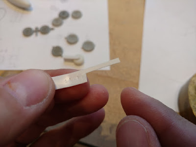
The tire has a unique tread pattern detail, much like a rounded diamond. I do a quick test by grinding the tip of a brass rod itno this shape and embossing with a hammer. This will work. More on this later.


The retraction arm is hacked out. Pivot points will need to get moved around, so the arm can clear the tire when fully retracted.


Gear door is paper. I'll use these dimensions to make the nice parts for the final model.


Studies of the swing arm.


I'll use large styrene rod stock as the rounded bits on each end. Three .100 styrene strips are sandwiched together using double stick tape. One end has an opening for a .250 disc, the other .312.


The part I want as the swing arm is between the two holes. I make three sets (the other two are back ups). One is cut off.


Remember, this made of 3 layers of .100 styrene. The extra material is not cut off until the arm is completely shaped. This acts as a handle during shaping.


Slowly grinding away. Not the metaphorical kind.


Here are the three layers pulled apart.


The arm needs to be thinner, I make a sanding jig to thin down the two outer arm sections.


Sand down flat to the jig.


Like so.


Here are the three sections together. The middle one gets chopped, creating the space between the forks for the tire.


Like so. That's it for now, more fun with bits of plastic in a few days, we'll finish the swing arm and make a tire!

Ghale Garmillon!
Wednesday, August 9, 2017

Oscar Goldman Builds The DMB-87: PART 7

Damn Goldman's vinyl loafers all to hell! Let's get started:


This will become a heavy model, as such to keep it from sagging over time, I am incorporating a metal infrastructure. From where the wheel touches the ground, through the wing and into the fuselage is not a straight line. Figuring out the inner dog leg re bar will take some planning.


1 to 1 spats of the ship are printed and cut out.


ABS rod stock is shaped on the lathe.


I hack out a riser to go around the spat so I can vac-u-form halves.


Parts are pulled in .100 thousands styrene.


They are cut out and sanded to fit together.


The leg is made of two sections of .100 thick styrene. The line where they meet becomes a reference for shaping. It also allows me to easily drill the channel through the center for the brass support rod.


Checking.


Here's what we have so far, putting things together like this is a good way to check if it looks right or not.


Here is one half of the landing gear leg, showing the channel. The cross section is rounded at the front and tapers at the trailing edge.


This presents a problem. The .092 brass rod is too close to the surface at the lower section that meets up with the spat.


Various solutions are thought out to solve this. If the model were a one off this would not be such a thorny issue, however casting a bunch means the solution has to take into account constant replication of  making the brass parts.


Again, printing out an internal side view helps. A straight brass support is the easiest. I elect to move it forward as far as possible (away from the rear trailing edge). You can see here how then the support rod must then angle sharply through the landing gear support. Not shown is how it must angle again into the display base. (Many of my mental gyrations and experiments have been omitted here. About half of my time creating these models is spent figuring out stuff like this. This model has a number of added complexities).


Here is the improved leg with the .092 brass support running through it.


To get a perfect fit of the spat and leg, sandpaper is attached to the spat and used to sand it's mirror profile onto the leg.


The spat is curved in both directions where the two parts meet. To create the second curved profile, first I Sharpie the surface black. A round motor tool bit is then used to shape.


 What you see here is the basic leg part being set up to be cast in resin. The two plastic pincer handles on either side are casting sprues. The hooked brass rod is an insert that creates the .092 channel in the part during casting.


Here is the completed mold (I did not document the mold construction). You can see the insert pin sticking out the side. The resin part is cast around it. It is pulled out leaving a perfect hole in the center of the part. The idea is to create one master part for the shared landing gear legs. This part will be further modded to create the master part.


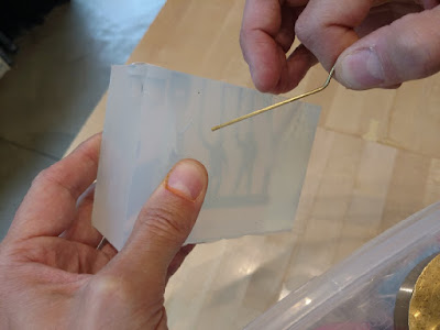
The silicone is clear, you can see the resin inside.


Once the resin has cured, the insert pin is removed before the mold is opened up.


I only need a few of these. Also in the mold are some modified figures for another project.


Here is the other project, a Marine F-4. I typically have several modeling projects running at once.


The casting.


The leg casting and leg after preliminary shaping. Next up: Gear doors, the landing strut, wheel...interior detail...  To quote H. Solo: "No reward is worth this!". Cheers!


Tuesday, August 8, 2017

Oscar Goldman & Ninja Cat Build The DMB-87: PART 6

Nationals all done, funds exhausted, basement almost tidy...time to for another dumb header:


Last we left off I got the basic fuselage knocked out. The fuse attaches to the MDF bar for machining, I decided in my finite wisdom to cut the bar. The wood glue is to glue it back. The post in the bar fits between the tail spikes to hold it on center.


Illy is used to create tail outlines, I stretched them because they are foreshortened in a top view.


They are double-stuck to a jig to create 23 degree angles.


These are scrapped.


New set, The holes are drilled before they are cut out, they are used to realign if I need to put them together to cut something. Notches on the ends are for the Garmillas protuberances.


I cut more positioning blocks to make sure everything is lined up.


Holes are drilled in tails while together and edges square.


Then 23 degree angles are cut.


Paper templates scale the wing roots.


Sharpen the ends of the brass pins to scribe a line on wing.


Drill holes.


The pure music of infrastructure.


I attach fuse to the MDF rail in order to mill the areas where wing roots attach flat for a nice fit.


Basic shape of wing traced.


On the model. Now that these dimensions are set (no details yet, they only cloud the mind), time to think about other wing areas.


There is ordinance and the racks to consider. The rest of the wing and those pesky spatted landing gear.


That's it for now, until next time (soon, I have still a lot of catching up to do here).