Pages

Monday, July 17, 2017

Oscar Goldman Builds The DMB-87: PART 5


In this installment we welcome help from B. Page.


A view with more of the plastic bits ground off. By constantly comparing it to the 1:1 print out of the blueprint it is possible to keep fidelity to the original artwork.


A cutout of the canopy dimensions has been placed on the model to visualize how that section is going to get made. Still figuring that one out, but I have some thoughts.


Using Illy I draw the cockpit. The placement of the pilots is done by reviewing the animation. The rear pilot is only partially seen in the episodes.


It's cut out 1:1...


...and placed on the model.


If you recall, space was left for the cockpit tub, three sections of .25 styrene is dropped in and cut to shape. A notch is cut for the placement of the rear ball turret.


The idea is to cast the fuselage as one part so I put into one of our pressure pots (used for resin casting) to see if it fits. Tight, but it will work.


More shaping of the fuselage, this view shows the bottom. Note the strake and engines.


Wing is part of the fuselage. The various slots in the fuselage sandwich are for these brass pins that will locate and support the wing. Here is a paper template of the wing to get this part rolling along. No detail gets added until all the basic structures are in place.


Here it is with paper wings. A lot of colluding lines and bulges. Everything has to get built at once so they interact properly.


Vaseline is brushed onto the fuselage (here it is taken apart).


Apoxie Sculpt is then used...


To fill in the void behind the turret.


Dry and sanded. The Vaseline keeps the Apoxie Sculpt from bonding, so that it can be removed if needed.

That's all for now. You can see me at the IPMS Nationals in Omaha. I'll be giving a swell Demo at 2pm on Thursday on resin kits. Hope to see you there.


Sunday, June 25, 2017

Oscar Goldman builds the DMB-87: PART 4


Last we showed the soul grinding joy of creating infrastructure. There is no glamour, indeed this is the nuts and bolts aspect of building that turns most builders off and puts bricks to sleep. Not me! I am totally in for the tedium. Let's get rolling:


A view of the bottom. There are a lot of subtle curves down here. Looking at drawings and the Bandai model are not enough to get it in your head, you have to dive in. I've added some engine nozzle facsimiles and a crude strake. The thrusters are squeezed in like pig guts in a casein. Lot of bulges and interrelated arcs. This is the main reason why the orthographic drawings are different from the 3D animation models. The 3D artist had his work cut out blending a Stuka and Phantom together.


I cut off the rear section of the fuse (I can't recall why now, I'm sure I had a good reason). I'm using a ball end mill to cut in half the channel for one of the main wing supports.


I double stuck on the top section and milled the other half of the channel. This is a quick way to match these up.


The section is then flipped over and a brass rod is put in the channel. Four holes are drilled to affix the rear fuselage section.


A quick shot under the hood showing the Adobe suite hard at work. Once the "size" of the images is set, they don't change. As I add various things they get added in. Here I'm working out the nozzle dimensions.


I rough some out in PVC...again a way of thinking about how these things will get made.


A more finished nozzle in ABS. This may end up being the final, but I can now work with this.


The outer nozzle section is made in two parts, there is a whole $#@*% of detail on the inside. I also consider how these will get cast in a way that the pour stubs can be easily removed without damaging the parts.


Throughout this build I am printing out sections of the plans. In this instance a side profile of the nose, which is cut out and used as a template to draw on the model.


The nose is attached with double sided tape (on center) to a block of wood. The block becomes a handle.


On the disc sander.


Using a different block I put the slopes on the sides. Get the big stuff off using this way, less wear and teat on your muscles.


The heat generated from the disc melts the plastic, so you have to watch carefully.


Starting to look like something.


Using some sculpey the engine bulges and canopy are blocked in. Just to see if things look kosher.

Well, that's it for now. The excitement mounts as bits of plastic become transformed!


BTW, two teasers here. Upper shows current state (blog is behind). Lower shows possible next 2199 project in 1/72nd scale.

AND you slackers out there, push those like buttons so I can afford kidney transplants for the kids. COMMENT because, I feel like I'm shouting into an empty room.

Wednesday, May 10, 2017

Oscar Goldman builds the DMB-87: PART 3


Hi, Oscar G. here sharing my modeling passion with my fellow modelers, no matter what our size differences are. Let's get on with it before my proud country goes into the wood chipper.


Digitized views are printed on cheap paper. The two 1/4 inch slabs of styrene are laid right on the print to figure out how to build up and down. This hearkens back to building balsa wood airplanes right on the blueprints using pins.


Imagine the void, the empty space that will be the cockpit. I build styrene walls around it to define the space.


Constantly check size and scale, a 1/48th scale pilot is checked to see if everything seems right. Two figures will end up in here. The idea is that this fuse will get cast in resin and the cockpit will get dropped in.


I attached a floor plate onto the bottom of the raw fuse slab to define the cockpit. In my infinite wisdom I chopped the fuselage slab to make room to locate the engines. The engines were keeping me awake...trying to figure out how to blend these things into the bottom of the fuselage. They are round when they exit the fuselage, but where they are in the fuselage they are flattened into the bottom of the ship. Anyway, I thought cutting the fuselage would get me where we needed to be.


Here you can see the slab attached to the MDF rail that gets clamped in the vise.


Here is the slab in the vise in the mill. The MDF rail is on center, the slab is my datum, anything on the blueprint could be located on the slab. Once all the locating information is cut into it, I can think about all the other stuff, the outer shape and sundry details. In this pic I am milling a slot to center the rear fuselage portion.


Again, the pesky engine placement. These are "dummy engines" made to sort out how they are going to get made.


Here are the squared up styrene blocks that will define the cockpit void. To the left of the pic is the front. The crenelations in the two side peices are an attempt to incorporate canopy details. Let's just say I didn't plan that part well, and even though they look spiffy, served no useful purpose. Fortunately, model building is also a process of expanding one's consciousness. The channel that cuts across the slab is for brass pins to locate the the wings.


You can clearly see the cockpit void in the front section on the left. The two rear fuselage slabs are at the right. Between them in the slot is a .125 styrene section that will become the strake between the engines. I couldn't think about it anymore, I just had to start building.


I drew the top view on, then rough cut out on the band saw.


Smoothed the sides on the disc sander.


Bottom view. There are times during building when it seems like a total drag. I remind myself, not to hurry. This IS the fun part. I have lots of models on my shelves. Many I have not looked at in a long time. Once the thing is done...onto the shelf. On to the next...

Friday, May 5, 2017

Oscar Goldman builds the DMB-87: PART 2

But First a Cold War Joke and after much laughing we will talk Datum Line:


In case your under 30, let me introduce myself, I'm Oscar Goldman and I'm scratchbuilding a DMB-87 in quarter inch scale. The "Snuka" is from the hit Japanese television show SPACE BATTLESHIP YAMAMMAMOMOTO 2199. (I always have to stop and think if its "Yamato" or Yamamoto", it's an occidental thing).


The orthographic plans are brought into Illy and carefully sized. I've been down this road before, so I am very careful to get everything properly scaled and all the layers with various views properly labeled. At some point you will end up with a lot of layers and they will all look the same. I know this is really dull and I sound like your mom. Fine. Make a mess, see if I care.


Here is a print out on 8 1/2x 11 paper, the lines are so I can cut the pages and register them. I end up printing out a lot of pages as I go along, doing it on standard sized cheap paper works well. The "Marquette" is made from foam core and is just a mental exercise to wrap my head head around how I'm going to build this thing. This ship has a lot of complex curves that all meet up in odd places. The wings and landing gear are pretty straight forward, they basically hang off the fuselage. The fuselage, however, has a lot of stuff: two frontal jowl rocket pods, chin scoop, cockpit, turret, six wing connections and two engines tucked underneath. There are flairs and bulges everywhere, a metal clad exhaust housing past the engine nozzles. The fuse terminates in a twin micro boom...


This is one of the reference pics, showing all the beautiful brain auguring complexity. When I'm looking at this I am trying to see how all the components are going to be located and hung off an imaginary datum line that runs through the design core. Sure, I could just whip out some oven baked clay and make a pattern, but how do all these remain symmetrical...proportional...straight... Believe it or not, this is fun for me. I'd rather make a Rubrics puzzle than solve one.


Here is an indication of what's going on inside my tiny brain. Everything relates to the fuselage, the core of the model. I draw a line that runs through the center, usually I refer to it as the "center line" or "zero line", the correct term is datum line.

Datum line: (engineering) A line which serves as a reference or base for the measurement of other quantities.

If this were a "studio" style model, the datum line usually doubles as the metal support armature. This model falls into the hobby kit world so will be created sans metal support armature. It's only 18 inches long, so we don't need to go crazy here anyway. (However, I am intending to cast in hard points of brass tubing as support so the model will not sag over time). Back to this illustration. Forget the surface detail, it's a distraction. Instead, think about the sub-assemblies. On the nose are two jowl rocket pods (see lines A and B, above). All that matters is how they get located onto the fuselage. Again, if you look at the animation pic from the show (above) do not be dazzled by the surface detail. Mentally break down the overall housing, the interior honeycomb holding the rockets, the forward rib extension and the lip around the opening. Now, imagine each part as emerging from a simple block of material. These blocks in turn are located to the fuselage via the datum line running through it's core.


From the start I'm thinking about the construction method of how this thing will get made. I can carve patterns from wood and vacu-form them to make shells. I can build up the under-structure using bulkheads and fill in the curved surfaces with epoxy. I can carve the whole thing out of styrene blocks. There are pros and cons to each. Vacu-forming will yield beautiful curved surfaces, but getting the parting line on this model will be challenging. Vacu-forms also shrink. It's also harder to nail the datum locators on the resulting shell. I seriously consider epoxy, but I'm worried about getting an even surface. Its also unclear if I can scribe panel lines. I settle on the styrene blocks. The thickest styrene I have is 1/4 inch, so multiple layers will have to be laminated together to get my shapes. However, these slabs will also serve as datum points for building. Styrene has the advantage of being easy to work with and the surface will accept detail lovingly. These drawings are meant to show how I think about the building inside out. The cockpit space is thought of as a void that will be walled around with styrene blocks. In block form centers can be located along the datum line, holes drilled to locate sub-assemblies and so on. The most complex part of this model are the engines. We will get to the details of this later, when it makes more sense.


I know enough bla bla and let's get building! Here are two slabs of 1/4 inch styrene, rough cut that will become the basis of the fuselage.


They are glued together with CA (super glue) instead of Weld-on liquid bonding solvent. This stuff can curl parts when it dries and shrinks.


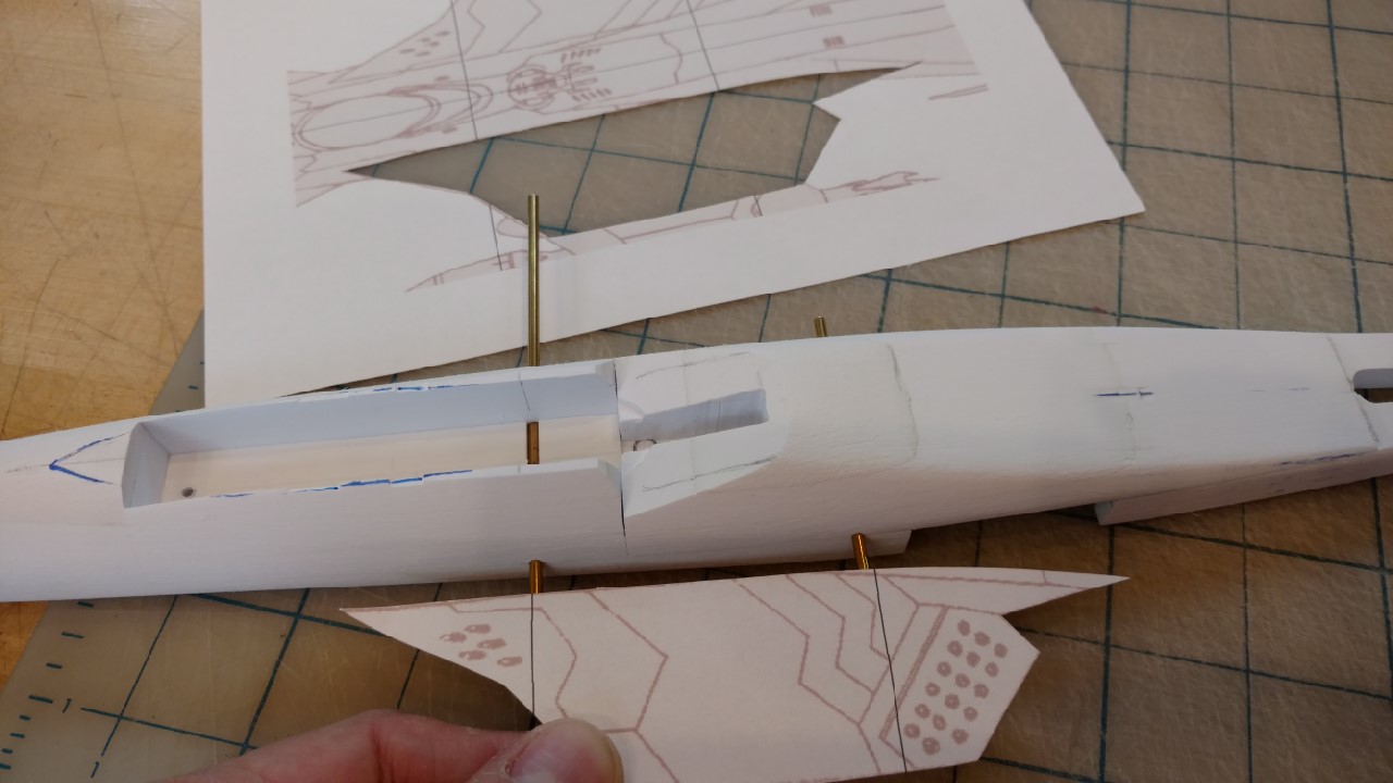
This is a horizontal slice of the fuselage. I cut out half a top view template and draw a slightly over sized outline using the center line. This is a visual reference only at this point, a sort of high altitude map.


Using screws, I then attach a strip of MDF on the bottom on center. This will be a handle of sorts, a reference to center when I put this into the mill to create the actual center line.


Of course, using the "mill" these days is like using carbon paper or a dial telephone, everything is spit out at the touch of a button by printers. The MDF rail on the bottom (clamped into the vice) will define the center line. This makes things easier as I go back to locate various elements.


Find center, zero it out, use the mill bit to cut both sides the same from center.

Join me next time as we get all transcendental and create the void.