

Teeth clean (see last post). Before I went any further on the leaf springs, I tossed out the kit wheels and found these in my box of all things small and Soviet. Not sure who made these, I have collected a lot of tires over the years. The rear tires they need to be paired up. I drilled them out and created a rear hub and cap. I'll use Grandt hex bolts to connect the two tires together. The Wheel hole is sized so it presses tightly onto the hub allowing me to fiddle around with alignment before glueing. The cap is a little vac-form. I decided to do it that way so I could make two that matched.

So, let's back up a minute....I built the Truck OOB as reference (can you believe I had three?). To get it all straight I use a large Lego panel. Legos are arrow square/straight and you can sight the lines easily to make sure all your alignment is so good it will make an IPMS judge cry. This arrangement also works very well for pesky aircraft landing gear and stabs.

Here are the two frames, the OOB is used as a reference to get the modded one right. I also checked my other references, the Toko model is spot on for dimensions (which only means they either got it right, or the guy who drew the blueprints copied the Toko model). Everything has to be kinda built at once, so you can see how its all going to fit together. Like, you know, synergy. 3, 4...whatever it takes. Because I'm trashing a lot on the modded one, I need to constantly be checking that things end up in the right spot. The frame also has a slight rake to it, It is really important to get this stance right in an unladen vehicle. (Even harder is to model an overloaded truck in which the frame is flattened out the rear leaf springs).

Behold, reference pictures! I would post the look of dismay my wife makes when she sees me pouring over sixteen pictures of a wheel (16 pictures and not one of the valve stem!), but I was only able to snap 2 before she turned away, not a proper reference at all. Ok, that one sounded much better in my head. Above, are pics of the vehicles leaf spring details (thank you, internet). When modding, I look at the real deal and/or look at pictures to guide what I will make. Blueprints only tell part of the story. They give you hard points for placement, the pics show you what it should look like.

Here you can see the rebuilt leaf springs. The kit attachment arm (on the left) was solid, I drilled and carved it to look like a multipart swing arm. I considered replacing the whole thing, but, the idea was to pick my battles and not build an entire replica in scale, right? You will notice brass u-shaped holder thingies....these turned out to be pretty challenging to build. There are actually 6 of these buggers on each rear unit, I simplified down to 4...
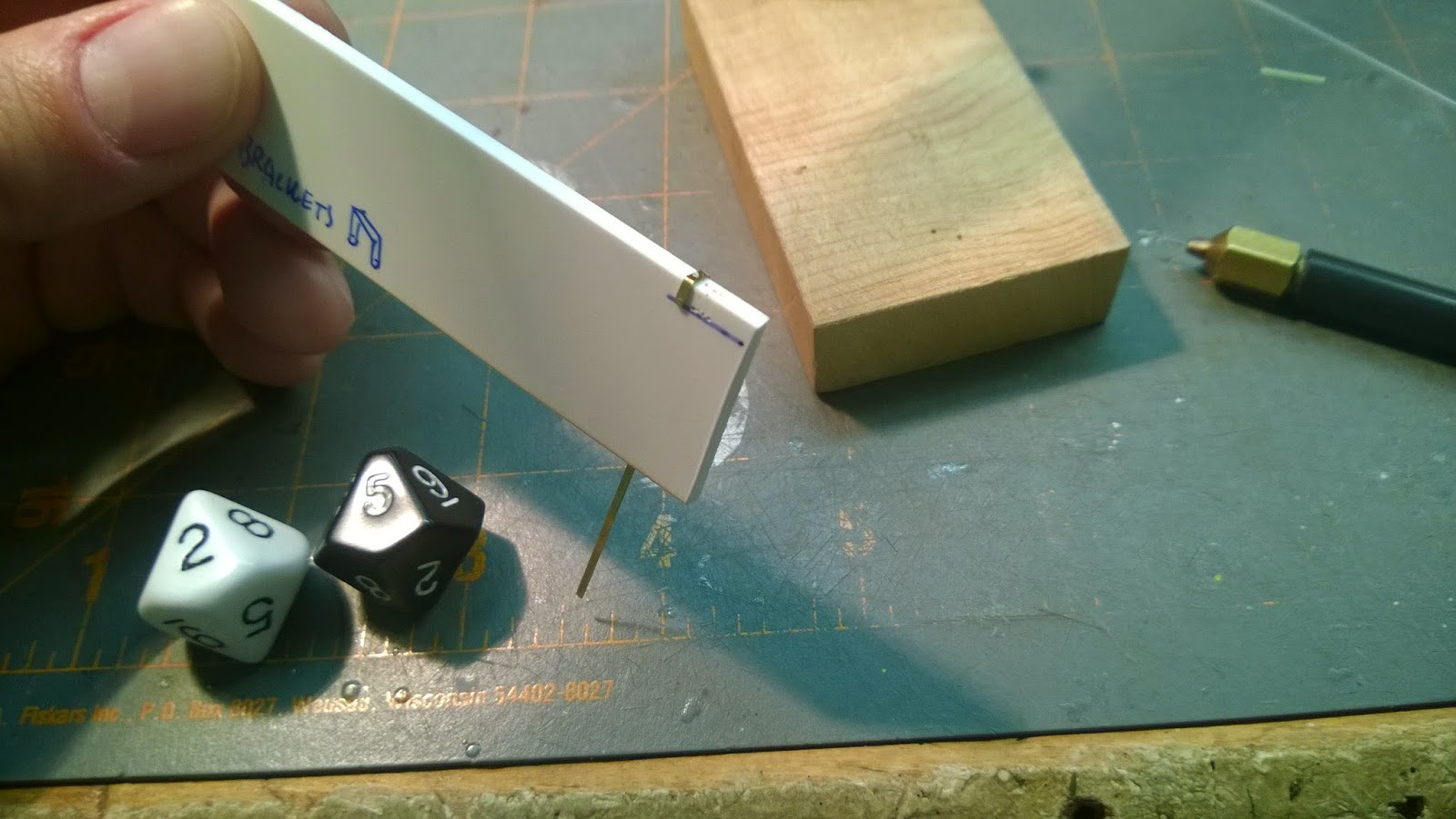
I wanted to build these things in plastic. They would be quicker to make and would bond to the plastic leaf unit easier. But, styrene strip cracks when you bend it, so it was a no-go. It would have to be brass. There needed to be 4 + 4 + 2 + 2 (12 total) that needed to look the same. This meant building a form that would allow me to bend/drill them. In this pick you can see the form I used to fold them and drill the bolt holes in the same spot. Each u-shaped bracket has 3 holes. The one on the bottom is used so I can put a plastic Grandt bolt through to secure to the leaf spring. There was not enough surface area to mate plastic and brass using super glue. I knew they would be popping off all the time because of the need to constantly manhandle the parts. So I made the connection a mechanical one.

There are a bunch of spacer plates to hold the shackles in place between the axel and spring units. I needed four identical plates. Using a caliper I measured the thickness of the leaf and axel. These measurements were used to find the relative centers on the plates. The dimensional lines are scribed onto a piece of strip stock markered with a black sharpie.

Using double stick tape, I make a sandwich of 4 layers. All are cut and drilled at the same time, so that they will be virtual clones.

Note, For the bottom layer I left the strip long, to use as a handle. Once all the shaping was roughed out, the parts are separated and cleaned up.

Here is an almost finished rear suspension unit. Certainly an improvement over the kit part. It will be partially obscured from view, but...well you can see it. Its a demo, right? See you next time in Doctor Tongue's Miniature House of Pain!
No comments:
Post a Comment