Pages

Showing posts with label Zis-5V. Show all posts

Tuesday, February 24, 2015

Zis-5V (1/35 MAC Models, Ukraine) Chapter 5


Before I go any further, I got my best reference out, and photocopy a side view drawing until it was 1/35 scale, based on accepted dimensions.  The model is put on this blueprint to align stuff.  In this case I am checking the positioning of the axels and cab front.  Better to know now.


Using the kit fenders as patterns, I cut out new ones in paper.  On the real vehicle they are tin sheet.  The Toko kit fenders look to be about the thickness of an ice cream sandwich.  I found no good pictures of what the area where the fender and hood sides meet.  A bunch of different angles meet up here.  This will probably be one of the most complex areas to deal with.  To solve, I begin building what I know with paper. The solution will come in the building.  And will inform me on what to look for in the reference so that I can get this are right.  This is the fun part.  Figuring it out.  Oh, yeah.


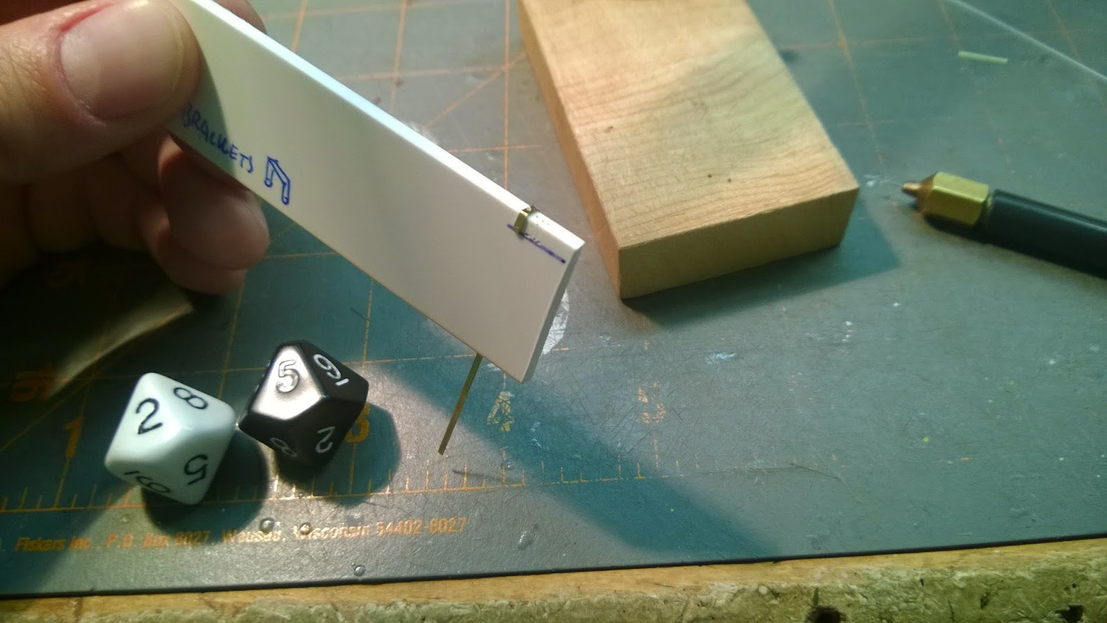
I really, really, really want to replace the side panels of the hood with ones that have actual louvers.  That you can see through.  Initially, I thought this was madness.  When I think something is not possible, I do a quick test to see.....turns out it is possible.  The big hurtle was being able to push the blade through the brass sheet. Trying to push it evenly all at once does not work.  But, if you imagine the blade is more like a shear and punch through on on end, then it works.  Tricky...but it works.  


I figured I may as well fashion the hood top from brass while I was at it.  If you have not used brass before, you should give it a try.  First, I made a plastic mannequin of the under hood area.  I made sure the horizontal support was centered.  I then folded a section of paper.  The fold will be my center line.


Double stick tape is put on the mannequin and the paper is made to conform, making sure the centers align.  excess paper is trimmed until I have a pattern.


A section of .005 brass sheet is carefully cut with a scissors.  A center line is drawn on the pattern and the paper pattern used to draw the correct shape.  The two square holes in the paper pattern allow me to align it to the center line drawn on the brass.


BTW, the brass sheet is "Shim Stock" and comes In various thicknesses.  (I just did a quick search using "Brass Shim Stock" as key words.  It comes in coil form and sheet).  The stuff I'm using is .005, which is about the same as PE parts.  If you are careful and draw accurate lines using a sharpie you can cut out parts very cleanly with a sharp scissors.  To create channels in the brass for folding, I lay a metal rule on the line and use a saw (upper right) to furrow out a groove.  Be patient, let the tool do the work.


Take your torch and anneal the brass by heating until it gets cherry red.  This will make it softer and more easily shaped.  If you have not ever annealed brass YOU HAVE NOT LIVED. 


Next. I took a thick sheet of plastic and used a round file to put a channel in it.  I taped the brass in place using double stick tape.  I then took a metal probe and gently coaxed the brass into the groove.


"Groovy"


I love brass, it is easy to shape, more durable and will impart a look and feel that plastic does not.  Here are the two parts for comparison.  Note, the curve of the brass hood can be easily altered to fit once the rest of the front is built.  Besides, building the hood in plastic is no cake walk either.


Now you see paper being used to get the shape of the next hood/cab section.  In the kit the sections all butt together, in real life the hood overlaps the front and rear sections.  because the brass is much thinner, it makes sense to overlap the sections the same way.  This will also allow for attachment underneath.


My patterns always have a center line as a reference.  In this case I draw both sides based off this center line, so they are mirror copies and make a symmetrical part.


Brass and plastic are not natural bonders, so I solder on some tabs that can be more easily joined to the plastic.


Here you can see the piano hinge being replicated in brass rod stock.  I have a unique process for soldering (which this pic is only a tease of).  I will post that process in more detail.  Basically: 1) I brush Flux onto both areas, 2) use a pliers to flatten solder and then cut into leetle rectangles, 3) hold the parts in place using clamps, sandwiching the tiny solder rectangles between them and finally 4) using a torch heat the area until the solder flows.  If you look at the pic closely above, you can see the trapped rectangles of solder.


Viola, almost finished!  Test fitting the side panels to see how it all works.  ALLWAYS test fit.  You don't want to spend 4 hours making the coolest part ever and discover it's .080 short.  Or maybe, you have issues and that's the fun.


Time to wrap up this post.  Before I go any further, I check the references and draw out any areas that will require attention.  Certainly this is true of the wind screens.  By drawing, it forces you to look.  Looking and seeing are the first steps to understanding.  Use the force baby. 


Monday, February 9, 2015

Zis-5V (1/35 MAC Models, Ukraine) Chapter 4


Teeth clean (see last post).  Before I went any further on the leaf springs, I tossed out the kit wheels and found these in my box of all things small and Soviet.  Not sure who made these, I have collected a lot of tires over the years.  The rear tires they need to be paired up.  I drilled them out and created a rear hub and cap.  I'll use Grandt hex bolts to connect the two tires together.  The Wheel hole is sized so it presses tightly onto the hub allowing me to fiddle around with alignment before glueing.  The cap is a little vac-form.  I decided to do it that way so I could make two that matched.


So, let's back up a minute....I built the Truck OOB as reference (can you believe I had three?).  To get it all straight I use a large Lego panel.  Legos are arrow square/straight and you can sight the lines easily to make sure all your alignment is so good it will make an IPMS judge cry.  This arrangement also works very well for pesky aircraft landing gear and stabs.

Here are the two frames, the OOB is used as a reference to get the modded one right.  I also checked my other references, the Toko model is spot on for dimensions (which only means they either got it right, or the guy who drew the blueprints copied the Toko model).  Everything has to be kinda built at once, so you can see how its all going to fit together.  Like, you know, synergy.  3, 4...whatever it takes.  Because I'm trashing a lot on the modded one, I need to constantly be checking that things end up in the right spot.  The frame also has a slight rake to it, It is really important to get this stance right in an unladen vehicle.  (Even harder is to model an overloaded truck in which the frame is flattened out the rear leaf springs).


Behold,  reference pictures!  I would post the look of dismay my wife makes when she sees me pouring over sixteen pictures of a wheel (16 pictures and not one of the valve stem!), but I was only able to snap 2 before she turned away, not a proper reference at all.  Ok, that one sounded much better in my head.  Above, are pics of the vehicles leaf spring details (thank you, internet).  When modding, I look at the real deal and/or look at pictures to guide what I will make.  Blueprints only tell part of the story.  They give you hard points for placement, the pics show you what it should look like.


Here you can see the rebuilt leaf springs.  The kit attachment arm (on the left) was solid, I drilled and carved it to look like a multipart swing arm.  I considered replacing the whole thing, but, the idea was to pick my battles and not build an entire replica in scale, right?  You will notice brass u-shaped holder thingies....these turned out to be pretty challenging to build.  There are actually 6 of these buggers on each rear unit, I simplified down to 4...


I wanted to build these things in plastic.  They would be quicker to make and would bond to the plastic leaf unit easier.  But, styrene strip cracks when you bend it, so it was a no-go.  It would have to be brass.  There needed to be 4 + 4 + 2 + 2 (12 total) that needed to look the same.  This meant building a form that would allow me to bend/drill them.  In this pick you can see the form I used to fold them and drill the bolt holes in the same spot.  Each u-shaped bracket has 3 holes.  The one on the bottom is used so I can put a plastic Grandt bolt through to secure to the leaf spring.  There was not enough surface area to mate plastic and brass using super glue.  I knew they would be popping off all the time because of the need to constantly manhandle the parts.  So I made the connection a mechanical one.


There are a bunch of spacer plates to hold the shackles in place between the axel and spring units.  I needed four identical plates.  Using a caliper I measured the thickness of the leaf and axel.  These measurements were used to find the relative centers on the plates.  The dimensional lines are scribed onto a piece of strip stock markered with a black sharpie.


Using double stick tape, I make a sandwich of 4 layers.  All are cut and drilled at the same time, so that they will be virtual clones.


Note, For the bottom layer I left the strip long, to use as a handle.  Once all the shaping was roughed out, the parts are separated and cleaned up.


Here is an almost finished rear suspension unit.  Certainly an improvement over the kit part.  It will be partially obscured from view, but...well you can see it.  Its a demo, right?  See you next time in Doctor Tongue's Miniature House of Pain!


Friday, February 6, 2015

Zis-5V (1/35 MAC Models, Ukraine) Chapter 3

Now that we (the "Royal We") have some idea of what needs attention on this relic, it's time to start it up.


There are big notches in the frame for the cab.  Oversized sections of styrene are cut and fit into place.  Often it seems like on kits like this either there is no alignment, or way over the top alignment.


Soft, yet brittle.  How do they do it?  It is much easier to fill the void with an oversized part and then trim down to fit.  As you can see the end of the frame broke, this will be fixed.


Test fitting.  This is an overlooked process....one must test fit, test fit and...test fit.  Especially models that have non-existent engineering.  Even Tamiya. 


I decided in my finite wisdom to replace the leaf springs rather than fix them.  The have very large knock outs on them and look like they were carved from cheese.  I only wanted to reuse the hardware for mounting to the frame.  I would then make new leaf thingies and the monting hardware to the chassis.  (Is that logical?  Logic, get thee behind me!)  Use a chisel blade and chop off a little at a time.  Its just like working with wood...take off a little at a time.


We want to leave the bottom leaf and mounting hardware behind as a basis for the new part.  Call it laziness. From a sheet of thick plastic (.125) I cut the inside profile of the reduced kit part and stuck it on with double stick tape.  Now that my thin/fragile part had a handle, I can file down properly.


Another view of the reduced part.  You can build it all from scratch, but that's not the point of this demo.  It's to highlight what can be done to existing kits.  In it's commie heart the Toko kit is really a good kit.


The leaf springs are a non-standard width, so I could not use standard stock.  I have this very fancy strip cutting tool that I use to cut strips.  This Zis has 6 leaf spring units, the two in the front are narrower than the rear four.  I always cut many extra than I need.  Legos are good for tools, they are square and easy to get.


Use the existing leaf spring to make notes on sizes of each part.  I put notes on notecards, this size is easy to work with and use during construction.  It's also nerdy and pigeonholes me as one of them anal retentive rivet counting nut cases.  what ever.

On most models there are pairs of things.  When dealing with pairs, cut/make identical objects at the same time so they match.  In this case I am cutting leaf spring sections.


The leafs are gently glued in place with toob glue.  I didn't glue the crap out of them, there is always a chance your going to wanna take em' apart.  And I did at some point, so this worked out.  Then I just glued them back together.  At this juncture I am making the mounting hardware.  There are a number of blocks and spacers that I carved out of styrene strip.  They come in pairs, both should be made at the same time.  There is a u-shaped bracket with nuts on the end that holds the axle to the springs.  This is made from copper wire because it bends easily.


A lot of nice people on the web took a lot of swell photos of the real Zis truck.  I use them to get all the details right.  Well, not all the details, that would be crazy, these days I TRY and focus on the important details.  Always check for references before you start.  It is staggering what is online if you know the right search terms.  For really obscure things use Google and Wikipedia to translate into the source language.  For example searching "Zis" in cyrillic (ЗиС-5) will get you some cool stuff.  Cut and paste into Google.  Just watch Rusky sites with lots of flashing banners and women for sale.  Those sites often have trojans that wanna hop onto your hard drive.  Just be careful.  Right, time to get my teeth cleaned.  Until next time!


Monday, February 2, 2015

Zis-5V (1/35, MAC Models, Ukraine) Chapter 2

Playing a bit of catch up here, much is done, just figuring out best way to present.  In today's installment you will see what will be changed/improved for the Nats demo.


This is a build up OOB and will be used as a comparison to the improved version.  Much of the suspension frame work will disappear under the body, but you can be surprised as to what can be seen.  The guttyworks of these vehicles are pretty exposed, so putting in a bit of work here will reward any viewer with enough gumption to look closely.  Or earn you an extra whack with a frying pan from wifey.  My ears are still ringing, so ask me later.


Now the upper bits.  Originally I thought the hood and side panels were Ok, but once I got to them...thank you Sticky!  The all-styrene tires are not bad and this American type shows up in my references.  BUT, they have to go, they are not Russian enough.  A wiser person would never replace the wooden parts with actual wood.  I have always wanted to try this, so now is the time.  Of course, I picked a truck with a wooden cab, so we shall see how many whacks with the frying pan this earns me.  I know this is wayway overkill, but not only do I count bolt heads, I cut them off and reposition them so their sides are not all aligned.  Note the fire extinguisher on the front of the cargo box.  I have never seen evidence of even a holder for one in any photograph.  If anyone out there has a photo or manual showing this feature, let me know.

Wednesday, January 28, 2015

Zis-5v (1/35 MAC Models, Ukraine) Chapter 1


The photo of this beautiful truck comes from an unknown source on the web.  There is no logic behind why I like things Soviet.  I find that modern photos, like this one, are a good inspiration to capture that elusive "something" quality.  Used.  Imperfect.  Dirty.  Fragile.  Real.  Zis is short for Zavod Imeni Stalina or "plant of Stalin's name".  I seem to recall this vehicle was modeled after the US Autocar truck.  Wikipedia says it's origin is the Fiat F-15.  I will revise once I check my references.  In any case, this is the stripped down mid-war production version to save labor and materials.  Much of the cab is wooden, the fenders folded tin sheet and war versions only had a single headlamp.  It came in any color you wanted, as long as it was green. Simple and easy to maintain. Every one thinks the Germans were the masters of planning, reality shows the Soviets were better planners for the war by halting all new work on any vehicles not already in production. By doing this all their effort was focused on churning out what they knew would work.  Nothing fancy, like this truck.  (FYI, I did check what I think is my best reference, "Soviet trucks of WW2" a Tankograd Soviet special #2007.  Jim and Jochen state that the AMO factory was renamed ZIS in honor of Stalin in 1931.  The AMO 1 was based on the Fiat, the AMO 2 was based on the US Autocar truck.  The Zis-5V started production in 1942.  The "V" stands for Voenniy, or "military".  J & J claim 81,646 Zis-5V's were built during the Great Patriotic War.  Not bad for a crappy little truck).


The Kit I got for $5 dollars.  It's a Toko kit and you probably could toss into any IPMS event and empty the area in 15 seconds.  I have a big stack of plastic vehicles from that part of the world.  They are slowly being replaced by Miniart, Hobbyboss and Tamiya.


The sprues come wrapped in a peculiar thin plastic that is unsettling.  There are a number of sprues from what looks like some very tired tooling.   Unbagging is like opening a time capsule, you can almost smell the cigarettes.  Not unlike buying a model from someone on Ebay who has cats.  But I digress.


It almost looks as if the masters were actually made using a hammer and sickle.  Once the parts are removed, the sprue doubles as a screen to separate chaff from wheat.


Try the veal, I'll be here all week.  In reality this kit stacks up pretty well against some of it's contemporaries, such as Nitto, Airfix and Frog.  Why would anyone contemplate even building one of these dinosaurs?  Well, there are several reasons: 1) When you build something like this you really have no choice but to improve it.  These days the youngsters call this "modding" or "customisation", I call it craftsmanship.  2) Rebuilding forces you to look at the references, and you learn stuff, thus becoming a superior human, 3) There is a sense of accomplishment in spending 7 hours making a new muffler system and 4) I am using this model as a subject of a building demonstration at the Columbus 2015 IPMS Nationals.


 ...So here it is in all its bland gray glory.  Built OOB.  In the next post I will highlight using this build up what will be rebuilt.  The OBB kit will be put side by side with the upgraded one, so you can see the differences. (I have always wanted to do that to see if all the work is really worth it).  In addition, basic building techniques will also be called out.  The goal is not to turn people into mindless rivet count'n constructo robots...it is rather to lay out processes and make seen what is normally hidden.  And when you see it, you may say..."hmmm...I can do that".  Just remember, it's your model (IMFM) and forget all the swine out there and build it to have fun.  More on the swine, later.