


This will become a heavy model, as such to keep it from sagging over time, I am incorporating a metal infrastructure. From where the wheel touches the ground, through the wing and into the fuselage is not a straight line. Figuring out the inner dog leg re bar will take some planning.

1 to 1 spats of the ship are printed and cut out.

ABS rod stock is shaped on the lathe.

I hack out a riser to go around the spat so I can vac-u-form halves.

Parts are pulled in .100 thousands styrene.

They are cut out and sanded to fit together.

The leg is made of two sections of .100 thick styrene. The line where they meet becomes a reference for shaping. It also allows me to easily drill the channel through the center for the brass support rod.

Checking.

Here's what we have so far, putting things together like this is a good way to check if it looks right or not.

Here is one half of the landing gear leg, showing the channel. The cross section is rounded at the front and tapers at the trailing edge.

This presents a problem. The .092 brass rod is too close to the surface at the lower section that meets up with the spat.

Various solutions are thought out to solve this. If the model were a one off this would not be such a thorny issue, however casting a bunch means the solution has to take into account constant replication of making the brass parts.

Again, printing out an internal side view helps. A straight brass support is the easiest. I elect to move it forward as far as possible (away from the rear trailing edge). You can see here how then the support rod must then angle sharply through the landing gear support. Not shown is how it must angle again into the display base. (Many of my mental gyrations and experiments have been omitted here. About half of my time creating these models is spent figuring out stuff like this. This model has a number of added complexities).

Here is the improved leg with the .092 brass support running through it.

To get a perfect fit of the spat and leg, sandpaper is attached to the spat and used to sand it's mirror profile onto the leg.

The spat is curved in both directions where the two parts meet. To create the second curved profile, first I Sharpie the surface black. A round motor tool bit is then used to shape.

What you see here is the basic leg part being set up to be cast in resin. The two plastic pincer handles on either side are casting sprues. The hooked brass rod is an insert that creates the .092 channel in the part during casting.

Here is the completed mold (I did not document the mold construction). You can see the insert pin sticking out the side. The resin part is cast around it. It is pulled out leaving a perfect hole in the center of the part. The idea is to create one master part for the shared landing gear legs. This part will be further modded to create the master part.

The silicone is clear, you can see the resin inside.
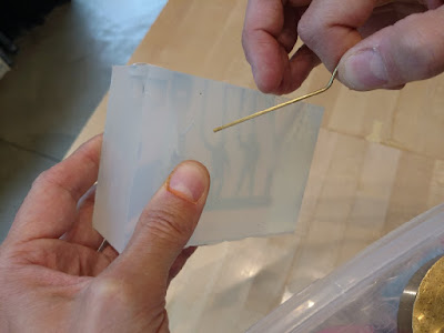
Once the resin has cured, the insert pin is removed before the mold is opened up.

I only need a few of these. Also in the mold are some modified figures for another project.

Here is the other project, a Marine F-4. I typically have several modeling projects running at once.

The casting.

The leg casting and leg after preliminary shaping. Next up: Gear doors, the landing strut, wheel...interior detail... To quote H. Solo: "No reward is worth this!". Cheers!
No comments:
Post a Comment