

No calls from DV or AS.
Aw well.


Another test link in. This is to get a feel of the flexible joint that will be needed.

The tolerances and dimensions all need to be worked out. Here is a drawing to scale, to work this out. There will need to be several tool jigs made.

Getting closer to a final design. These links are cut from strips of 36" long 1/2 inch wide brass. Tubing is .062 with .040 interior dimension. Off the shelf stock is used to simplify the number of operations needed on each part.
More tomorrow....so tired...

Before the link design is completed I make a place-holder drive wheel to make sure everything can work together.

A close up of the maquette tack unit. There are several things I'd like to capture in the brass units: 1) The smooth conveyer like feel, 2) The simplicity, and 3) the zig zag patterns which appear as a detail on the faces and sides. Technically this link design is inconsistent with the Freman logic I have created. This logic is akin to a Russian, in that everything is simple so as to be fixable in the field. These tracks have a dedicated left and right, which would create enormous supply issues, but I have decided the look is more important.
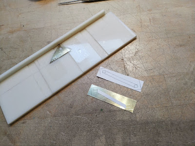
Here is the first jig. Each blank track link is slid into the matching depression. The triangular brass on the jig has the square hole, a scriber is used to scratch the shape on each end by flipping the part. This is a trick that makes sure the scribed design is exactly the same on both ends of the link.
 A link. The "zig" on top is another strip of brass. It is soldered in place. There is still much to be done before the link is complete. However, I'm still thinking out the process and how to streamline. Making a few test parts is the best way to get through this.
 Here is another tool in the system, basically a "vice" that holds the upper "zig" in place so I can solder with a torch.
 A look at the whole thing so far. You can see a full link in the jig to be scribed and a second jig to scribe the cut lines on the "zigs".
 5 links on the maquette. Always check what you are doing. Especially in processes that require a lot of time. Not only that, I constantly check to see if the part matches my aesthetics.

Here is the first jig. Each blank track link is slid into the matching depression. The triangular brass on the jig has the square hole, a scriber is used to scratch the shape on each end by flipping the part. This is a trick that makes sure the scribed design is exactly the same on both ends of the link.


No comments:
Post a Comment